Earthing resistance and number of rods for isolated earth pit without buried earthing strip the earth resistance of single rod or pipe electrode is calculated as per bs 7430.
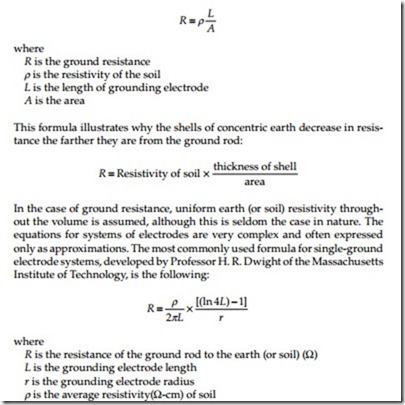
Ground rod resistance formula.
R1 resistance of one ground rod n total rods in layout k combining factor rn total net resistance of grounding system r measured earth to ground resistance using ieee 4 point method p 38 30 r for 10 ground rods 19 15 r or 38 30 r for 20 ground rods k 378 log n 89.
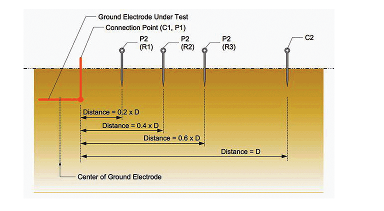
You can only do this by using the fall of potential method with a three terminal earth ground resistance tester.
Step 1 connect your length of wire to a metal stake in the ground.
If your ground rods are placed at least one rod length apart you can use a formula to estimate the earth resistance of multiple grounding rods.
If this is the case for your ground rod the best solution is to drive a different rod into a different location.
Use the above formula to approximate the ground resistance of a system and not as a replacement for actual ground measurements.
L total length grounding grid conductors 4 x 200 6 x 150 6 x 50 2000 meters.
However we can estimate the resistance to ground using scenario b.
R p 2 pi l ln 4l a 1 p 2 pi s 1 l squared 3s 10x8 2l 10 4 5s 10 4 where.
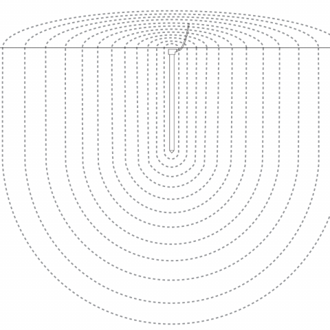
You should measure the resistance of an electrode with respect to the surrounding soil in the area.
ρ resistivity of soil ω meter l length of electrode meter d diameter of electrode meter example.
In some instances ground rods can be installed in areas where the earth has a lot of resistance.
Hi slamat thank you for your question regarding resistance to ground calculations for parallel electrodes it is our pleasure to help.
R resistance p soil resistivity l length.
For instance if a ground rod is driven into a very rocky and dry area it may not conduct electricity into the ground well.
Multiple ground rods yield a lower resistance to ground than a single rod.
Ground ring ground rods.
P2 and c2 connect to a separate all metallic grounding point like a water pipe or building steel.
With this method the resistance of two electrodes in a series is measured by connecting the p1 and c1 terminals to the ground electrode under test.
Calculate the upper limit of ground resistance rg of the grid if soil resistivity is 180 ω m for a ground grid shown in below figure.
In areas where driving ground rods may be impractical the two point method can be used.
For example the national electric code requires no greater than 25 ohms of resistance in a ground system.
Run the wire to your test location.
The total burial length is the combination of the horizontal and vertical conductors in the grid as well as the ground rods.
Make sure that you have stripped back the insulation from both ends of the wire to allow for a good connection.
So if you are using 10 foot ground rods you must place.